
freeCodeCamp

By Chloe Tucker
This article explains the Open Systems Interconnection (OSI) model and the 7 layers of networking, in plain English.
The OSI model is a conceptual framework that is used to describe how a network functions. In plain English, the OSI model helped standardize the way computer systems send information to each other.
Learning networking is a bit like learning a language - there are lots of standards and then some exceptions. Therefore, it’s important to really understand that the OSI model is not a set of rules. It is a tool for understanding how networks function.
Once you learn the OSI model, you will be able to further understand and appreciate this glorious entity we call the Internet, as well as be able to troubleshoot networking issues with greater fluency and ease.
All hail the Internet!
You don’t need any prior programming or networking experience to understand this article. However, you will need:
Over the course of this article, you will learn:
Here are some common networking terms that you should be familiar with to get the most out of this article. I’ll use these terms when I talk about OSI layers next.
A node is a physical electronic device hooked up to a network, for example a computer, printer, router, and so on. If set up properly, a node is capable of sending and/or receiving information over a network.
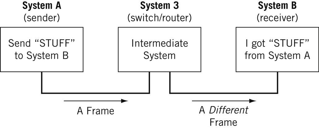
Nodes may be set up adjacent to one other, wherein Node A can connect directly to Node B, or there may be an intermediate node, like a switch or a router, set up between Node A and Node B.
Typically, routers connect networks to the Internet and switches operate within a network to facilitate intra-network communication. Learn more about hub vs. switch vs. router.
Here's an example:

Source
For the nitpicky among us (yep, I see you), host is another term that you will encounter in networking. I will define a host as a type of node that requires an IP address. All hosts are nodes, but not all nodes are hosts. Please Tweet angrily at me if you disagree.
Links connect nodes on a network. Links can be wired, like Ethernet, or cable-free, like WiFi.
Links to can either be point-to-point, where Node A is connected to Node B, or multipoint, where Node A is connected to Node B and Node C.
When we’re talking about information being transmitted, this may also be described as a one-to-one vs. a one-to-many relationship.
A protocol is a mutually agreed upon set of rules that allows two nodes on a network to exchange data.
“A protocol defines the rules governing the syntax (what can be communicated), semantics (how it can be communicated), and synchronization (when and at what speed it can be communicated) of the communications procedure. Protocols can be implemented on hardware, software, or a combination of both. Protocols can be created by anyone, but the most widely adopted protocols are based on standards.” - The Illustrated Network.
Both wired and cable-free links can have protocols.
While anyone can create a protocol, the most widely adopted protocols are often based on standards published by Internet organizations such as the Internet Engineering Task Force (IETF).
A network is a general term for a group of computers, printers, or any other device that wants to share data.
Network types include LAN, HAN, CAN, MAN, WAN, BAN, or VPN. Think I’m just randomly rhyming things with the word can? I can’t say I am - these are all real network types. Learn more here.
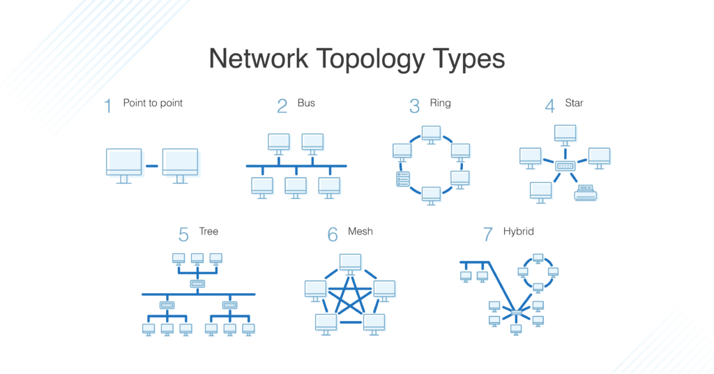
Topology describes how nodes and links fit together in a network configuration, often depicted in a diagram. Here are some common network topology types:

[learn more about network topologies here](https://www.dnsstuff.com/what-is-network-topology">Source + What is the OSI Model?
The OSI model consists of 7 layers of networking.
First, what’s a layer?

Source
No, a layer - not a lair. Here there are no dragons.
A layer is a way of categorizing and grouping functionality and behavior on and of a network.
In the OSI model, layers are organized from the most tangible and most physical, to less tangible and less physical but closer to the end user.
Each layer abstracts lower level functionality away until by the time you get to the highest layer. All the details and inner workings of all the other layers are hidden from the end user.
How to remember all the names of the layers? Easy.
Keep in mind that while certain technologies, like protocols, may logically “belong to” one layer more than another, not all technologies fit neatly into a single layer in the OSI model. For example, Ethernet, 802.11 (Wifi) and the Address Resolution Protocol (ARP) procedure operate on >1 layer.
The OSI is a model and a tool, not a set of rules.
Layer 1 is the physical layer. There’s a lot of technology in Layer 1 - everything from physical network devices, cabling, to how the cables hook up to the devices. Plus if we don’t need cables, what the signal type and transmission methods are (for example, wireless broadband).
Instead of listing every type of technology in Layer 1, I’ve created broader categories for these technologies. I encourage readers to learn more about each of these categories:
The data unit on Layer 1 is the bit.
A bit the smallest unit of transmittable digital information. Bits are binary, so either a 0 or a 1. Bytes, consisting of 8 bits, are used to represent single characters, like a letter, numeral, or symbol.
Bits are sent to and from hardware devices in accordance with the supported data rate (transmission rate, in number of bits per second or millisecond) and are synchronized so the number of bits sent and received per unit of time remains consistent (this is called bit synchronization). The way bits are transmitted depends on the signal transmission method.
Nodes can send, receive, or send and receive bits. If they can only do one, then the node uses a simplex mode. If they can do both, then the node uses a duplex mode. If a node can send and receive at the same time, it’s full-duplex – if not, it’s just half-duplex.
The original Ethernet was half-duplex. Full-duplex Ethernet is an option now, given the right equipment.
Here are some Layer 1 problems to watch out for:
If there are issues in Layer 1, anything beyond Layer 1 will not function properly.
Layer 1 contains the infrastructure that makes communication on networks possible.
It defines the electrical, mechanical, procedural, and functional specifications for activating, maintaining, and deactivating physical links between network devices. - Source
Fun fact: deep-sea communications cables transmit data around the world. This map will blow your mind: https://www.submarinecablemap.com/
And because you made it this far, here’s a koala:

Source
Layer 2 is the data link layer. Layer 2 defines how data is formatted for transmission, how much data can flow between nodes, for how long, and what to do when errors are detected in this flow.
In more official tech terms:
There are two distinct sublayers within Layer 2:
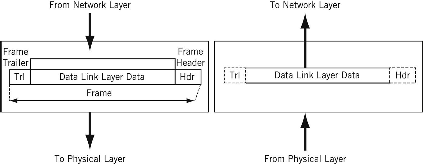
The data unit on Layer 2 is a frame.
Each frame contains a frame header, body, and a frame trailer:

Source
Typically there is a maximum frame size limit, called an Maximum Transmission Unit, MTU. Jumbo frames exceed the standard MTU, learn more about jumbo frames here.
Here are some Layer 2 problems to watch out for:
The Data Link Layer allows nodes to communicate with each other within a local area network. The foundations of line discipline, flow control, and error control are established in this layer.
Layer 3 is the network layer. This is where we send information between and across networks through the use of routers. Instead of just node-to-node communication, we can now do network-to-network communication.
Routers are the workhorse of Layer 3 - we couldn’t have Layer 3 without them. They move data packets across multiple networks.
Not only do they connect to Internet Service Providers (ISPs) to provide access to the Internet, they also keep track of what’s on its network (remember that switches keep track of all MAC addresses on a network), what other networks it’s connected to, and the different paths for routing data packets across these networks.
Routers store all of this addressing and routing information in routing tables.
Here’s a simple example of a routing table:

Source + learn more about routing tables here
The data unit on Layer 3 is the data packet. Typically, each data packet contains a frame plus an IP address information wrapper. In other words, frames are encapsulated by Layer 3 addressing information.
The data being transmitted in a packet is also sometimes called the payload. While each packet has everything it needs to get to its destination, whether or not it makes it there is another story.
Layer 3 transmissions are connectionless, or best effort - they don't do anything but send the traffic where it’s supposed to go. More on data transport protocols on Layer 4.
Once a node is connected to the Internet, it is assigned an Internet Protocol (IP) address, which looks either like 172.16. 254.1 (IPv4 address convention) or like 2001:0db8:85a3:0000:0000:8a2e:0370:7334 (IPv6 address convention). Routers use IP addresses in their routing tables.
IP addresses are associated with the physical node’s MAC address via the Address Resolution Protocol (ARP), which resolves MAC addresses with the node’s corresponding IP address.
ARP is conventionally considered part of Layer 2, but since IP addresses don’t exist until Layer 3, it’s also part of Layer 3.
Here are some Layer 3 problems to watch out for:
Many answers to Layer 3 questions will require the use of command-line tools like ping, trace, show ip route, or show ip protocols. Learn more about troubleshooting on layer 1-3 here.
The Network Layer allows nodes to connect to the Internet and send information across different networks.
Layer 4 is the transport layer. This where we dive into the nitty gritty specifics of the connection between two nodes and how information is transmitted between them. It builds on the functions of Layer 2 - line discipline, flow control, and error control.
This layer is also responsible for data packet segmentation, or how data packets are broken up and sent over the network.
Unlike the previous layer, Layer 4 also has an understanding of the whole message, not just the contents of each individual data packet. With this understanding, Layer 4 is able to manage network congestion by not sending all the packets at once.
The data units of Layer 4 go by a few names. For TCP, the data unit is a packet. For UDP, a packet is referred to as a datagram. I’ll just use the term data packet here for the sake of simplicity.
Transmission Control Protocol (TCP) and User Datagram Protocol (UDP) are two of the most well-known protocols in Layer 4.
TCP, a connection-oriented protocol, prioritizes data quality over speed.
TCP explicitly establishes a connection with the destination node and requires a handshake between the source and destination nodes when data is transmitted. The handshake confirms that data was received. If the destination node does not receive all of the data, TCP will ask for a retry.
TCP also ensures that packets are delivered or reassembled in the correct order. Learn more about TCP here.
UDP, a connectionless protocol, prioritizes speed over data quality. UDP does not require a handshake, which is why it’s called connectionless.
Because UDP doesn’t have to wait for this acknowledgement, it can send data at a faster rate, but not all of the data may be successfully transmitted and we’d never know.
If information is split up into multiple datagrams, unless those datagrams contain a sequence number, UDP does not ensure that packets are reassembled in the correct order. Learn more about UDP here.
TCP and UDP both send data to specific ports on a network device, which has an IP address. The combination of the IP address and the port number is called a socket.
Here are some Layer 4 problems to watch out for:
The Transport Layer provides end-to-end transmission of a message by segmenting a message into multiple data packets; the layer supports connection-oriented and connectionless communication.
Layer 5 is the session layer. This layer establishes, maintains, and terminates sessions.
A session is a mutually agreed upon connection that is established between two network applications. Not two nodes! Nope, we’ve moved on from nodes. They were so Layer 4.
Just kidding, we still have nodes, but Layer 5 doesn’t need to retain the concept of a node because that’s been abstracted out (taken care of) by previous layers.
So a session is a connection that is established between two specific end-user applications. There are two important concepts to consider here:
Sessions may be open for a very short amount of time or a long amount of time. They may fail sometimes, too.
Depending on the protocol in question, various failure resolution processes may kick in. Depending on the applications/protocols/hardware in use, sessions may support simplex, half-duplex, or full-duplex modes.
Examples of protocols on Layer 5 include Network Basic Input Output System (NetBIOS) and Remote Procedure Call Protocol (RPC), and many others.
From here on out (layer 5 and up), networks are focused on ways of making connections to end-user applications and displaying data to the user.
Here are some Layer 5 problems to watch out for:
The Session Layer initiates, maintains, and terminates connections between two end-user applications. It responds to requests from the presentation layer and issues requests to the transport layer.
Layer 6 is the presentation layer. This layer is responsible for data formatting, such as character encoding and conversions, and data encryption.
The operating system that hosts the end-user application is typically involved in Layer 6 processes. This functionality is not always implemented in a network protocol.
Layer 6 makes sure that end-user applications operating on Layer 7 can successfully consume data and, of course, eventually display it.
There are three data formatting methods to be aware of:
Learn more about character encoding methods in this article, and also here.
Encryption: SSL or TLS encryption protocols live on Layer 6. These encryption protocols help ensure that transmitted data is less vulnerable to malicious actors by providing authentication and data encryption for nodes operating on a network. TLS is the successor to SSL.
Here are some Layer 6 problems to watch out for:
The Presentation Layer formats and encrypts data.
Layer 7 is the application layer.
True to its name, this is the layer that is ultimately responsible for supporting services used by end-user applications. Applications include software programs that are installed on the operating system, like Internet browsers (for example, Firefox) or word processing programs (for example, Microsoft Word).
Applications can perform specialized network functions under the hood and require specialized services that fall under the umbrella of Layer 7.
Electronic mail programs, for example, are specifically created to run over a network and utilize networking functionality, such as email protocols, which fall under Layer 7.
Applications will also control end-user interaction, such as security checks (for example, MFA), identification of two participants, initiation of an exchange of information, and so on.
Protocols that operate on this level include File Transfer Protocol (FTP), Secure Shell (SSH), Simple Mail Transfer Protocol (SMTP), Internet Message Access Protocol (IMAP), Domain Name Service (DNS), and Hypertext Transfer Protocol (HTTP).
While each of these protocols serve different functions and operate differently, on a high level they all facilitate the communication of information. (Source)
Here are some Layer 7 problems to watch out for:
The Application Layer owns the services and functions that end-user applications need to work. It does not include the applications themselves.
Our Layer 1 koala is all grown up.

Learning check - can you apply makeup to a koala?
Don’t have a koala?
Well - answer these questions instead. It’s the next best thing, I promise.
Congratulations - you’ve taken one step farther to understanding the glorious entity we call the Internet.
Many, very smart people have written entire books about the OSI model or entire books about specific layers. I encourage readers to check out any O’Reilly-published books about the subject or about network engineering in general.
Here are some resources I used when writing this article:
Chloe Tucker is an artist and computer science enthusiast based in Portland, Oregon. As a former educator, she's continuously searching for the intersection of learning and teaching, or technology and art. Reach out to her on Twitter @_chloetucker and check out her website at chloe.dev.